Introduction
Leon Theremin built the first theremin in 1920. Since then many attempts have been made to copy, simplify or improve the original instrument. The currently available theremins can be divided into the following three groups as described below: the music instruments, the noise-making kits and the theremin alike. My idea with the Open.Theremin was to build an affordable, modular and playable theremin instrument. Also it should be open to everyone and DIY (do it your self).
Theremin Instruments
There are theremins on the market that can be played as real instruments. These theremins show impressive performance, have both loop antenna (volume) and rod antenna (pitch) and adjustment possibilities. They are mostly based on analogue circuits with coil resonators. Like most high quality music instruments these theremins are relatively expensive with prices in the range of $350-$1,500. Examples are the famous Moog Music Etherwave Theremins. The cheaper real Theremins with both pitch and volume antennas are smaller, provide less options and often come as build-it-yourself kit for $150-$300 (PAiA Theremax Theremin, B3 Theremin).
Noise-making Theremin Kits
Then there are the low cost theremin kits (<100$). Most of them are pitch only theremins. Some are analogue circuits, some are built with digital integrated circuits. These theremins are great to build as a DIY project and are fun to play with. Due to the missing volume antenna, the non linearity and the relatively short reception range it is hard to play real music on these devices. And often the sound is far from the original sinus wave of a theremin. Examples are the Junior Theremin £11.65, the Minimum Theremin Kit 80$ or the Silicon Chip Theremin.
Theremin Alike
Finally there are some interesting attempts to build devices with a theremin alike interface based on modern technology. These theremins use sensors like laser distance sensors or ultrasonic reflection sensors to measure the distance of the hand to the device and play a corresponding sound. Of course the result is not the same as that of the original theremin principle where even the slightest movement of one finger will change the signal.
How everything started
So now that I knew I wanted to build a simple and modular theremin instrument I started building a prototype. Since I have never built a theremin before I started looking at different circuits in the internet. The analogue circuits are complicated, require special parts like coils and are not flexible. The digital circuits are simple but the sound and antenna range is not so good. I decided to go for a digital resonator (or two) combined with a micro-controller to improve the sound and the range. I imagined once I get a good signal from the resonator I can easily capture it with the controller, correct the reception curve and and generate the sound I want. And this is how I developed the open.theremin instrument.
First Prototype
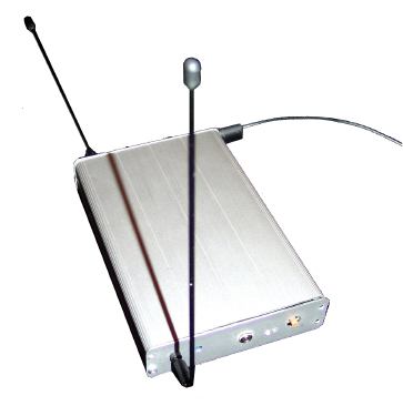
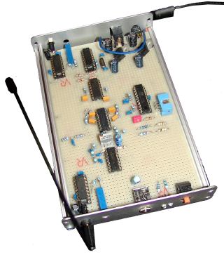
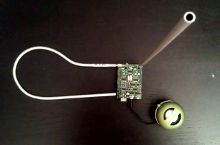
First open.theremin prototype
The prototype above does it all. The digital resonator uses basically the same principle as good old theremin. There is a hand sensitive oscillator, a reference oscillator, a mixer to find the difference of the two resonators and a filter and amplifier.
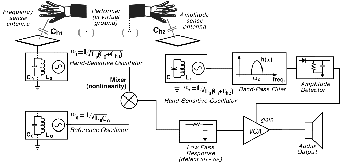
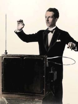
Original Theremin Principle
The Resonator Circuits
The first difficult part was to find the most stable resonator circuit for both, the fixed frequency as well as for the variable oscillator. I tested many circuits from the internet and selected the ones that I liked most. I put a collection of them together with some insights on the Oscillators page on this site.
The Signal Capture
The second challenge was to capture and measure the signal. Not that it was impossible to measure a sawtooth signal frequency with a micro-controller, the thing was that I always had in mind that the theremin should be simple and affordable. So I set up a system with a low-cost ATTiny261 and used only standard OpAmps and some resistors to do the job.
The Programming
Third the programming of the micro-controler to get a clean signal without glitches and digital noise was tricky. The routine I got now is quite simple and the antenna range is definitely improved by some simple calculation and software filtering. I think there are many possibilities to further improve the theremin by smart coding and I can imagine many fancy new features to be added in future. For now I implemented a free waveform generator, two control voltage outputs and auto calibration on startup.
Surface Mounted Devices (SMD)
It may sound strange at first, but to simplify the rebuild of the theremin and also to further reduce the price (smaller PCBs, cheaper parts) I decided to do all in SMD. Once you know how to do the DIY-Reflow Soldering SMD is quick and fun. We have done it on workshops with many people without prior knowledge and even with self etched PCB - all theremins worked perfectly.
Modular Setup
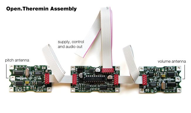
When I finished the first prototype on an experimental board I was quite happy with the quality and the setup. Only thing that the circuit was not so simple and no so easy to share as I expected. So I decided to split the circuit up into two units. By splitting off the resonator unit (Open.Theremin.RC) it is now possible to build this unit as a simple, stand alone, digital theremin. Also this part can be used two times, once for the pitch side and once for the volume side. The other unit (Open.Theremin.UP) holds the micro-controller and the amplifiers. Later on I added a alternative resonator unit using an coil-capacitance (LC) resonator (Open.Theremin.LC). So now the Open.Theremin is a modular system with further advantages as described in the System Overview section.
Arduino Based Design
With all the experiences made in the development of the RC and LC resonator circuits and the use of micro controllers in digital theremins I decided to totally rework the system. It should be more easy to build, assemble and program. To simplify and make it more easy to program I decided to base the new design on the popular Arduino board. Two LC resonators and a new audio chip are compacted onto a so called shield for the Arduino. The Open.Theremin.UNO - The real Theremin on Arduino was born. With all the experience and valuable ideas from early community members I could complete the design in only a few month and the improvements and simplifications are significant.
The Open.Theremin.UNO became really successful and people around the world started playing it.
Design Version 3
With more people playing the theremin I got feedback on the playability and on the design. And that's how I could further improve it by adding more buttons to change parameters during play and by simplifying the assembling with a fully automatic calibration function. Niclas Roy, designer and artist from Berlin, redesigned the interface and the logo.
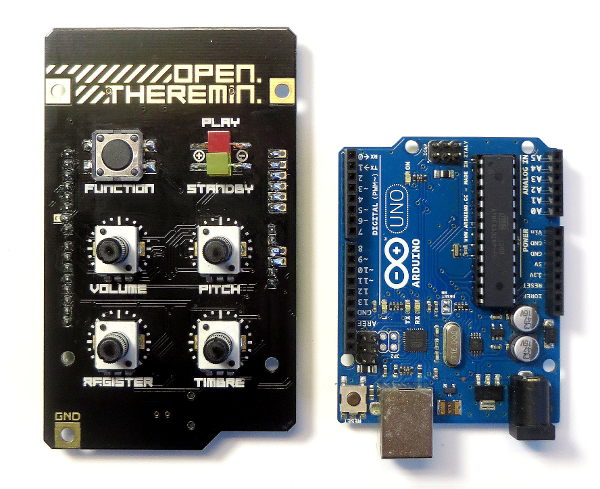
The Open Theremin V3 was very popular and people around the world built it and play it.
Documentation of the OpenTheremin V3:
- Instructions
- Schematics
- MIDI Implementation
- Housings
OpenTheremin V4
The latest version of the OpenTheremin integrates all the electronics in one elegant circuit that makes up the whole instrument. The design was realized in collaboration Danish designer Peter van der Beek, a young and uprising designer from the Design Academy Eindhoven. With two channel control voltage, full automatic calibration and a sensor button the newest design features many new improvements and clearly shows the OpenTheremin has become a mature Theremin instrument.
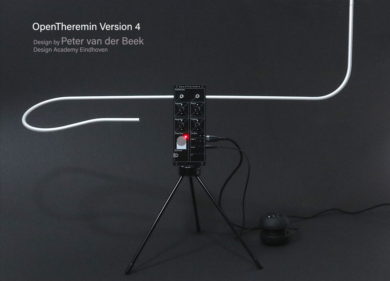
Newest boards are now available in gaudishop.ch for you.
The new form factor of the OpenTheremin V4 allows integration into a Eurorack system and opens up many new possibilities.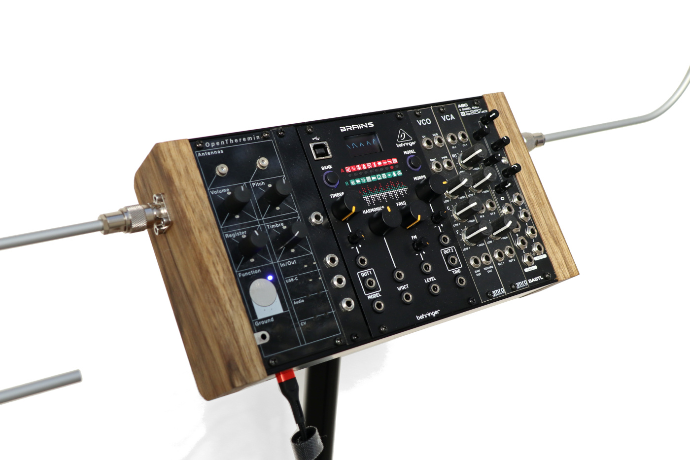
First prototype of a modular OpenTheremin. Build instructions here.
An OpenTheremin Eurorack kit is now available at gaudishop.ch


