Open.Theremin.LC Schematic
Click on image for larger PDF Version.
Circuit description Open.Theremin.LC
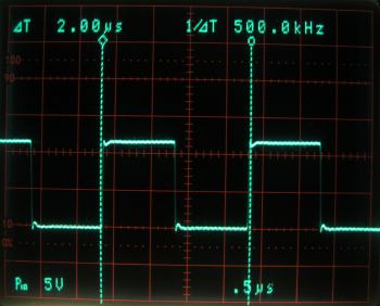
The open.theremin.LC, like the original theremin, consists of a reference oscillator and a hand sensitive variable oscillator. Top left on the schematic and on the board the reference oscillator of the open theremin can be found. It is built using a crystal quartz of 16 Mhz and a 14 stage counter to divide the frequency down to a fixed frequency of 500 kHz. This frequency is output at O4 (pin 5) of the integrated circuit HEF4040 (U1) and can be measured at the test point 1 (TP1). The ground frequency of the quartz oscillator (16 Mhz) is also used to clock the micro controller board and the 31.25 kHz frequency found at O6 (pin 13) is used by the controller as a sampling frequency. The open.theremin.LC circuit is used twice in a full theremin, for the pitch and for the volume antenna. The two circuits are exactly the same. To avoid any interference between the two antennas one board however runs at a slightly different frequency (14.74 Mhz). The components that differ are indicated with an asterisk (*) in the part list. TP1: reference frequency of 500 kHz. The variable oscillator on the bottom left of the schematic and of the circuit board is a simple LC oscillator built around a digital inverter HEF4069 (U11). The coil L1 (1000 uH) and the capacities (C30 and C31) define the oscillation frequency of about 500 kHz. The oscillator is sensitive to the capacity of the hand to the antenna. To tune the circuit there is a variable capacity (TC1) in parallel to the bulk capacities. The resistor "Option 2" does not need to be assembled in this configuration (Option 1). Option 2 (untested) is meant to tune the circuit using a potentiometer rather than a variable capacitor. The variable frequency can be be measured at test point 2 (TP2) and should be pretty much the same as the frequency on TP1 when properly tuned. The frequency variation induced by the hand capacity (of a few pico farad) is in the range of some kilo hertz. TP2: variable frequency of 500 kHz with little variations when approaching the antenna. The difference of the reference and the variable frequency is built by the mixer, in this case the xor gate HEF4077 (U3). The signal output by the mixer at pin 3 can be measured at test point 3 (TP3). TP3: Mixer signal Bottom right on the schematic and on the circuit is the filter to make a nice triangle signal from what is output by the mixer. The active filter uses the operational amplifier TL072 (U4). A good filtering is important for the signal to be measured precisely by the micro controller. Any remaining high frequencies on this signal will induce jitter to the consecutive measurement. The variable triangle signal can be measured at test point 4 (TP4). Adjust the variable capacitor (TC1) to adjust the signal. TP4: Triangle output signal. The whole LC board is powered with DC voltage by the connector K1 or by a separate power connector and stabilized by 10uF condenser C5. All circuits are decoupled by a 100nF condenser (C1 to C4). These are important to avoid any additional oscillations theremins are quite sensitive on.


